RFID Tag Antennas
Introduction
RFID tag antennas are designed for a unique purpose, and their design can actually reveal some information about the tag itself. Below are a few things you can usually learn from looking at an RFID tag:
- Its frequency: You can discover whether the tag is Low Frequency, High Frequency, or Ultra-High Frequency, and then have a general idea of the tag’s read range.
- If the tag is a Far-Field tag and if it has additional Near-Field capabilities.
- If it is a UHF Dipole - the type of dipole antenna used: Fat, Meandered, or Tip-Loaded.
Frequency
Generally, if you know what to look for it is pretty easy to detect the frequency at which the tag operates just by examining the tag. That is because the correlation between the tag antenna design and the way the tag talks to the RFID reader/antenna will reveal the frequency. Below, the three main frequency types are outlined, including information about each and their typical antenna design:
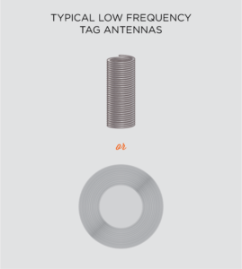
Low Frequency (LF)
Frequency: 125 – 135 kHz - generally, 124 kHz, 125 kHz, or 135 kHz
Read Range: Touch to 45.7 cm (18 in) under ideal conditions
Coupling Technique: Inductive coupling – reader’s antenna generates a magnetic field to activate an electric current in the tag’s antenna
Antenna Design: Typically, circularly coiled tag antenna
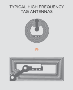
High Frequency (HF)
Frequency: 13.553 – 13.567 MHz - generally, 13.56 MHz
Read Range: Touch to around 1.5 m (5 ft.) under ideal conditions
Coupling Technique: Inductive coupling – reader’s antenna generates a magnetic field to activate an electric current in the tag’s antenna
Antenna Design: typically, rectangular or circular-shaped, small tag antenna
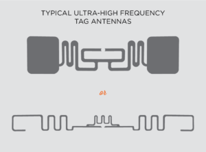
Ultra- High Frequency (UHF)
Frequency: 400 – 1000 MHz - generally, 860 – 960 MHz
Read Range: Up to 35 m (115 ft.) under ideal conditions
Coupling Technique: Backscatter coupling – reader’s antenna generates RF energy to activate the RFID tag, which modulates the information and reflects the remaining energy back to the reader antenna.
Antenna Design: Typically, dipole-shaped tag antenna
Near-Field Capabilities: If it has a small loop-shaped antenna in the middle, it usually has near-field capabilities.
UHF Structure & Materials
Most UHF tag antennas are designed with a dipole-type structure. This means they generally are long and thin visually, and operate similar to a magnet. The similarity is apparent because they have two ‘open’ ends, or poles, for the energy to build up and, consequently, allow a current flow to the Integrated Circuit (IC), or chip.
The most well-known RFID tags on the market that are not structured like a typical dipole antenna are tags similar to the SMARTRAC Frog and the Alien Spider. These tags are square-shaped in order to best display their omni-directional properties and are sometimes called “dual-dipole” tags. Learn more about Dual Dipole RFID Tags in our article "Dual Dipole UHF RFID Tags".
Tag antennas are made from a metal wire or metallic sheet in order to provide an adequate conductor for the RF energy. Then, depending on the type of tag, other types of materials like PET, plastic, paper, and polyester are used to provide the base around the tag antenna.
Terms to Know
AC – an electrical current that sometimes changes its direction, usually 50 to 60 times per second.
DC – an electrical current that flows constantly in one direction.
Resistance - the property of a particular material to resist the flow of electrons. Occurs in AC and DC circuits.
Inductance - the property of an electric conductor that causes an electromotive force to be generated by a change in the current flow.
Capacitance - the ability of a body to store electric charge.
Resonance – a state achieved when the inductance and capacitance cancel each other out.
Reactance – the property of a particular material to resist the change in flow of electrons, only in AC circuits. Below are two different types of reactance:
Inductive Reactance – the ability to store energy in the form of a magnetic field. Below is the equation:
ω (Angular Frequency) = 2πF
XL = 2πFL = ωL
Capacitive Reactance - the ability to store energy in the form of an electric field. Below is the equation:
ω (Angular Frequency) = 2πF
XC = 1 ÷ (2πFC) = 1 ÷ (ωC)
Impedance – the combination of resistance and reactance.
UHF Dipole Lengths
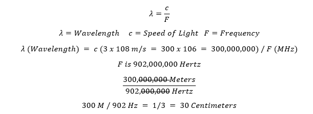
The length of a UHF dipole antenna is one way to effectively classify that type of dipole. Three common dipole lengths exist: Half-Dipole, Modified Half-Dipole, and Short-Dipole. In order to distinguish the difference, first the wavelength typically associated for UHF RFID tags must be found:
Half-Dipole – A Half-Dipole’s length is equal to one-half of the wavelength. With a UHF tag, a typical size for a half-dipole is around 16.4 centimeters (164 mm) or anywhere between 16 and 17 cm. These are typically not used in RFID applications because the tags would be too long and tend to have resistance problems.
Modified Half-Dipole – A Modified Half-Dipole’s length is usually around 9.2 cm (92 mm). This length is convenient because most printer labels are around 10.6 cm (106.2 mm) so the tag can easily fit on or in them. Because a length shorter than a half-wave dipole has a negative reactance, several things have to be modified to make this shorter antenna work. These tag antennas can also be referred to as “Dipoles” or “Resonant Antennas”.
Short Dipole – A Dipole that is typically 1/10 of the wavelength in size is referred to as a Short Dipole. These are much smaller than Half-Dipoles and have to be modified greatly in order to work well because of their size.
Dipole Types
Because Modified Half-Dipoles are smaller than half of a typical UHF wavelength, they have a negative inductance and must be modified with additional capacitance to counter balance; or, inductance can be added, lowering their resonance to a lower frequency. Modifying these antennas is usually performed one or two of the following ways:

Fat – “Fat” dipoles, also called “Broadband” dipoles, are characterized by having the maximum amount of metal on the tag face. Increasing the amount of metal on the tag is achieved by etching or silver ink printing. By increasing the wire thickness, inductance is reduced, and the increased metal surface creates a large capacitance. Because these tags have a lot of metal, they are often best used on high dielectric surfaces like glass, wood, and plastic.
One of the most popular fat or broadband UHF tags on the market is Alien’s “G”. The Avery Dennison AD-661r6 is also a fat tag.
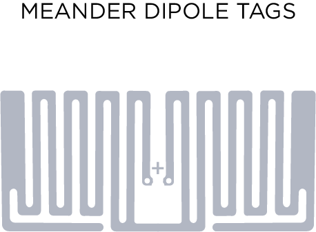
Meanders – Most people associate meanders with UHF RFID tags even if they do not know why the meanders are on the tag. Meanders are the typical product of folding the wire back and forth, creating peaks and troughs along the wire. These meanders are lengthening the actual wire without adding length to the tag. This means a wire length of a half-wavelength dipole (16.4+ cm) is possible while still being able to fit on a typical printed label (10.2 cm). The meanders lower the resonance and allow the tag to resonate at the preferred frequency.
Some of the most common examples of tags with meanders are the Alien Squiggle, the SMARTRAC ShortDipole, and the Avery Dennison AD-321r6.

Tip Loading – Tip Loading looks similar to a fat dipole and is usually used in conjunction with meanders in order to drop the resonance. Tip loading is adding metal through etching or silver printing to the ends of the dipole only. Adding wide metal ends to a dipole allows additional storing capacity for electric charges, which compensates for the reduced inductance because of the length.
A few common examples of this is the Alien Short, SMARTRAC DogBone, and the Avery Dennison AD-237R6.
Conclusion
If you would like to learn more about all things RFID, check out our website, our YouTube channel, comment below, or contact us.
To read more about RFID tag antennas, check out the links below!
Sources
Wikipedia. Capacitance and Inductance.
Laheurte, Jean-Marc; Ripoll, Christian; Paret, Dominique; Loussert, Christophe. UHF RFID Technologies for Identification and Traceability. Wiley 2014