RFID Antennas: Beamwidth & Directivity
Introduction
Even though RFID antennas are not the brains of an RFID system, they are still complex devices that can hinder or benefit an RFID system depending on the application and chosen antenna. For instance, choosing the wrong antenna for a certain application could result in inches of read range instead of feet. Besides the basic guidelines for choosing an antenna like gain and polarization, other factors exist that could take a system’s read range and results to the next level. Beamwidth and directionality are two core principles to grasp in order to make a more informed purchasing decision.
Beamwidth
Beamwidth is defined as “the angle between two points on the same plane where the radiation falls to ‘half power’, or 3 dB below the point of maximum radiation.”¹. It can also be thought of as the peak effective radiated power of the main lobe. Most usually think of beamwidth as the horizontal angle on a radiation pattern, but there are two beamwidths – azimuth (horizontal) and elevation (vertical).
Azimuth vs. Elevation
If the antenna is on a 3D plane, like below, you will be able to accurately see the azimuth and elevation beamwidths. Understanding the azimuth and elevation beamwidths of an RFID antenna enables a person to choose the best antenna for their application. In some applications, a very wide azimuth or elevation beamwidth is needed in order to read all the tagged items lined up in, for example, a small room. In other applications, like a conveyor belt, a thinner, acute beam is better fitted. Some antenna data sheets actually show the 3D model of the azimuth and elevation beamwidths, while other manufacturers’ data sheets show 2D models. The 2D models are more basic, but are still able to clearly show the beamwidth in both planes.
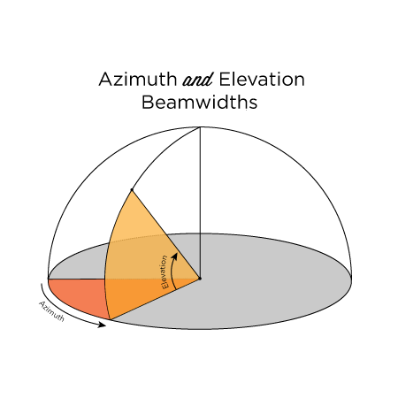
Azimuth and Elevation Beamwidths
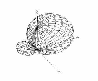
3D Radiation Pattern
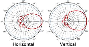
2D Radiation Pattern
Directivity
The directivity of antenna is defined as “its ability to focus in a particular direction to transmit or receive energy”¹. The way that an antenna directs its energy is a huge factor in both choosing an antenna and setting up an application. If an antenna is set up in an application and the type and radiation pattern is not known, the tagged items might not be read or be affected by absorption, diffraction, reflection, and refraction. Antennas can be grouped in two different sets based on directivity – isotropic or anisotropic, or omni-directional or directional.
Isotropic vs. Anisotropic
Another important concept to understand about antennas is there are two main types in terms of beams and directionality: isotropic and anisotropic. An isotropic antenna is one which emits an RF field uniformly in all directions. A perfect isotropic RFID antenna, or one that emits radio waves in general, doesn’t exist because the concept violates Maxwell’s equations. Even though there are no true isotopic antennas available to purchase, it is still beneficial to understand the concept because it can aid when learning about gain.
If gain is written as dBi instead of dBd it is being displayed over the value rate of an isotropic antenna. The true gain rating of an antenna is displayed in dBd. Because isotropic antennas radiate equally in all directions, portraying the gain in dBi is essentially just inflating it. In order to compare different antenna gains displayed in dBd and dBi, use the formulas below.
dBi = Antenna Gain in dBd + 2.14 dB
An anisotropic antenna just implies the opposite of isotropic and is defined as an antenna that radiates power differently and unequally in the elevation and azimuth fields. All antennas sold are anisotropic.
Isotropic Antenna Radiation Pattern
Omni-Directional vs. Directional
Omni-directional and directional antennas differ in the directionality of the beam. Omni-directional antennas are used mostly in proximity antennas but can be in other types as well. These antennas are built to increase the coverage of the azimuth plane and decrease coverage in the elevation plane; this is done by emitting RF power in a spherical pattern. In a 3D model, the beamwidth of these antennas look like a donut or a sphere and they usually have a mid-level gain.
Omni-Directional Antenna Radiation Pattern
Directional antennas are more common and usually have external antennas. Directional antennas emit concentrated RF power toward a targeted area. These antennas sometimes have an azimuth and elevation beamwidth of roughly the same degree in order to provide the perfect ‘beam’ of coverage. The beamwidth (azimuth or elevation) is determined directly by the gain of the antenna– the higher the gain, the more focused the beam. All types of directional antennas exist with different azimuth and elevation angles and gains. Understanding the beamwidth, gain, directionality, and how each of these interact to create a radiation pattern will help when choosing the best antenna for an application.
Both omni-directional and directional antennas are commonly sold on the RFID market. In an application where tagged items will be passing the antenna on different sides, or even near the back, an omni-directional antenna would be the best choice. Omni-directional antennas are also used in any application where a wide angle of coverage is needed. Directional antennas are great for applications where the tagged items will always be passing the same area at around the same height, like a conveyor belt. It is easy to think of directional antennas as more targeted antennas with cone-like beams.
Conclusion
For more information on beamwidth and directivity, comment below or contact us for more information.
For more information on all things RFID, check out our RFID resources page and our YouTube channel.
To learn more about RFID antennas, check out the links below!
¹CompTIA RFID+. Study Guide for Exam RF0-001. Paul Sanghera