A 3D Picture of an RFID Read Zone
RFID Read Zones
An RFID Read Zone is a term that describes the free space surrounding an RFID system in which an RFID tag can be read. A read zone varies in size and shape depending on a few factors like the RFID reader, power settings, the RFID antenna, antenna polarization, application environment, RFID tag, and tagged item.
Read zones are important to understand in order for an RFID application to be successful. For instance, if an RFID system is setup in a large doorway, but the tagged items are only read if they pass through the right side of the doorway, there is a high probability that only 50% of the tagged items will be read. In order to increase the read rate and thus the probability of reading all of your tagged items, it is important to understand the size and shape of the read zone, which is gained through testing.
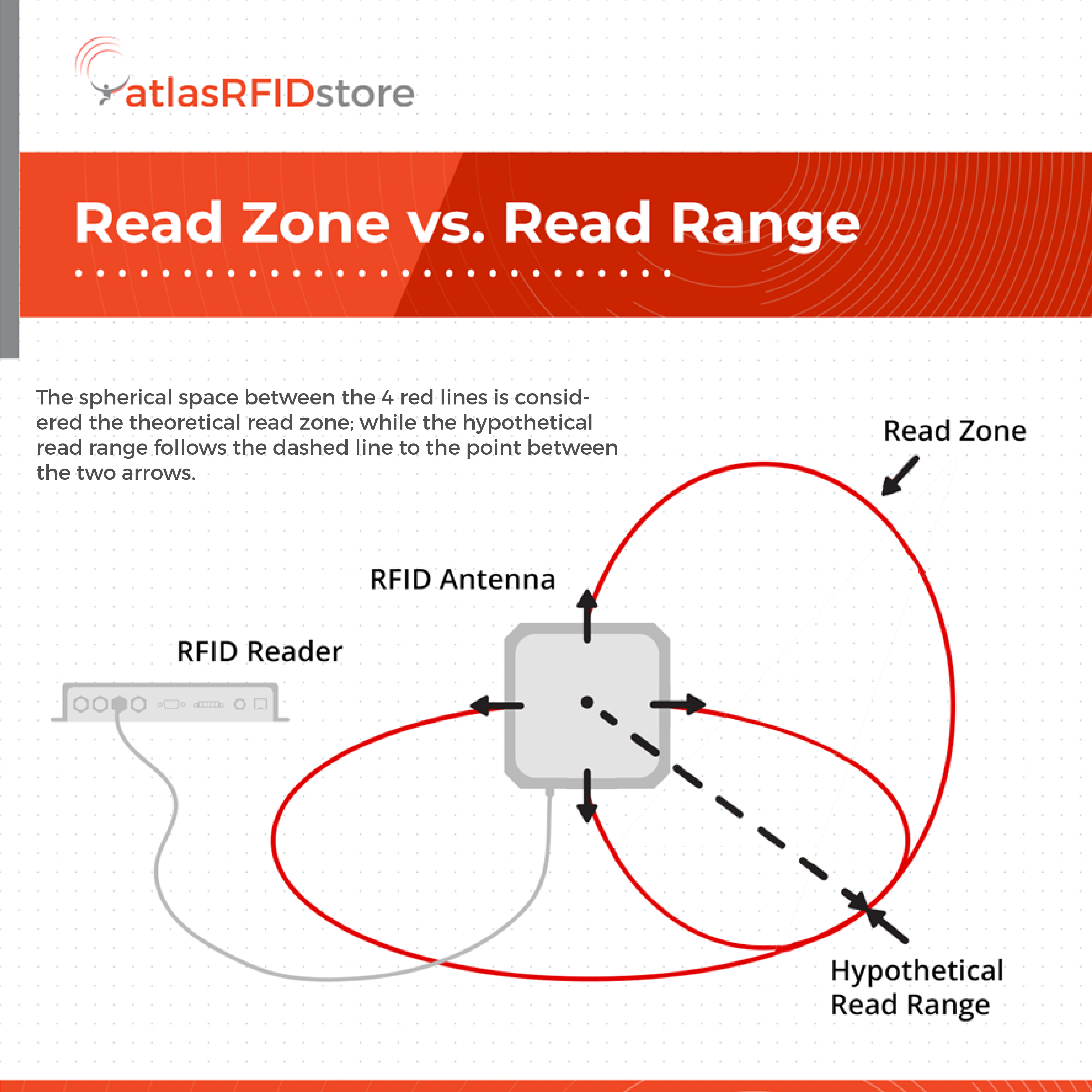
Many new RFID users confuse the term “Read Zone” and “Read Range”. While similar, these two terms are describing different things.
- Read Range – Read range describes the hypothetical range at which an RFID system can read a tag in a given direction in an ideal environment. When used in terms of RFID tags, it is the hypothetical range at which an RFID tag can respond in an ideal environment.
- Read Zone – Read zone describes a 3-dimensional area around an RFID antenna in which RFID tags can be read. Read zones are able to be mapped by using RF power mappers and can be configured by adjusting reader and antenna parameters. Additionally, zones can be adjusted as needed through the use of RF reflective or absorbing materials to create boundaries.
Though read range and read zone are different terms, an RFID system’s read range directly impacts the read zone. Unlike read range, a read zone is describing a range of coverage that extends around the RFID antenna with varying boundaries. The read range can generally be used to determine the hypothetical distance at which a tag can be read in the direct path of the RFID antenna.
The Correlation Between RFID Read Zones & RFID Antennas
The size and shape of a read zone depends on the RFID Antenna, which is why choosing the correct antenna for an application is vital. Antennas differ from each other in a few different ways, but three properties - Beamwidth, Directionality, and Gain - work together to make up the size and shape of the read zone.
- Gain - An RFID antenna’s gain is its Effective Radiated Power (ERP). Gain is commonly also described as how strong a signal can be sent or received in a given direction.
- Beamwidth - An RFID antenna’s beamwidth is the angular width of the antenna’s beam at half power. It is calculated by determining the angle on a horizontal and vertical plane to produce the respective Azimuth and Elevation beamwidths.
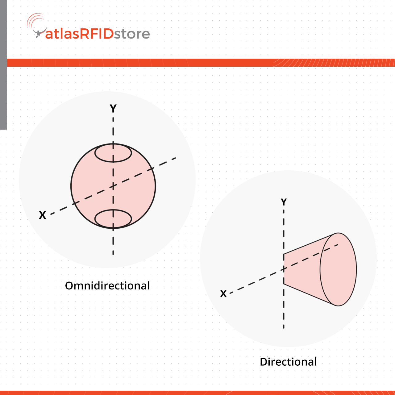
- Directionality - An RFID antenna’s directionality is simply defined as either directional or omni-directional. A directional antenna is one that emits a beam of RF energy in one direction, while an omni-directional antenna emits RF energy in all directions on one plane. From the top, a directional antenna visually looks like it’s emitting a cone of energy, while an omni directional antenna looks like it is emitting energy in a donut-like shape.
Read Zone Principles
There are four primary principles involved in creating a read zone:
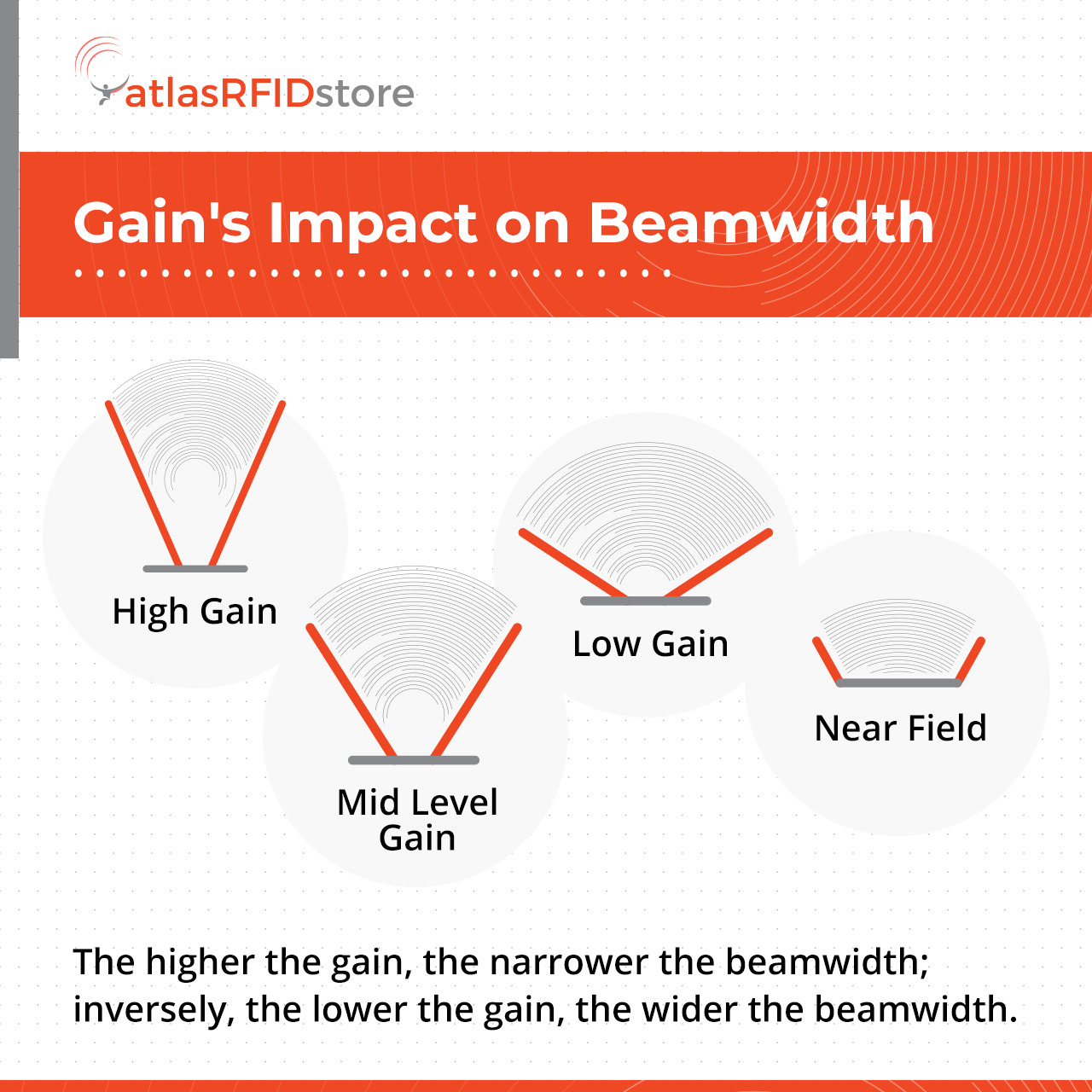
Principle #1: The higher the gain, the narrower the beamwidth, and inversely, the lower the gain, the wider the beamwidth.
Principle #2: The higher the gain, the longer the read range, if all else is equal.
Principle #3: Multipath (when two or more favorable radio paths exist between the antenna and the RFID tag) and common wave reactions (reflection, refraction, diffraction, and absorption) can create unpredictable results. Some areas inside the read zone will get no tag reads, and some areas outside the read zone will get unexpected tag reads.
Principle #4: Energy never stops. RF energy will pass the given or tested read range, but at that point, the energy is not strong enough to power an RFID tag. When diagramming the read zone, the border will be defined as where the RF energy stops being strong enough to activate the RFID tag.
Mapping An RFID Read Zone
Mapping out an RFID read zone is important to ensure that all tagged items will be inside or pass through the read zone in order to be read. If tagged items are not read, the application and its data will not be accurate, which is why testing is critical.
An RFID read zone can be mapped out using an RFID power mapper, or an RFID tag or tagged item. When mapping out a read zone, it is strongly advised to do so in the exact area and environment in which the potential system will be located, because the surrounding environment will affect the read zone. Constructive and destructive interferences, also called null and dead spots, can be identified and mitigated so that they do not interfere with the application.
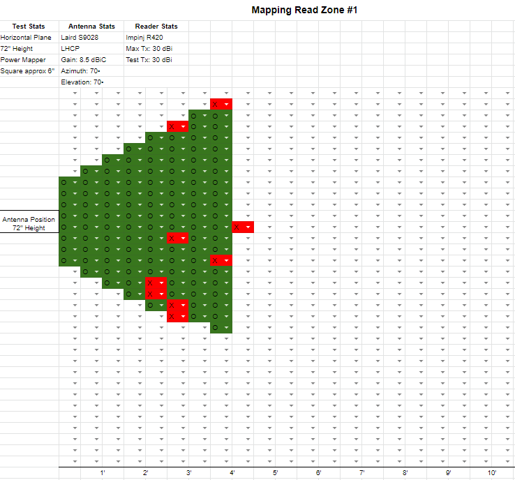
A read zone can be mapped out in different ways depending on the application and the read zone size. If tagged items will not be passing through in a consistent location/area, it is recommended to map out the application area using a paper and pencil, or a custom excel document.
In this example, we used a spreadsheet and the features “Data Validation” and “Conditional Formatting” to create these custom cells that change color when they are filled with an ‘X’ meaning no read, or a ‘O’ meaning readable. In the examples below, the first example is mapping on a horizontal plane, and the second example is mapping on a vertical plane.
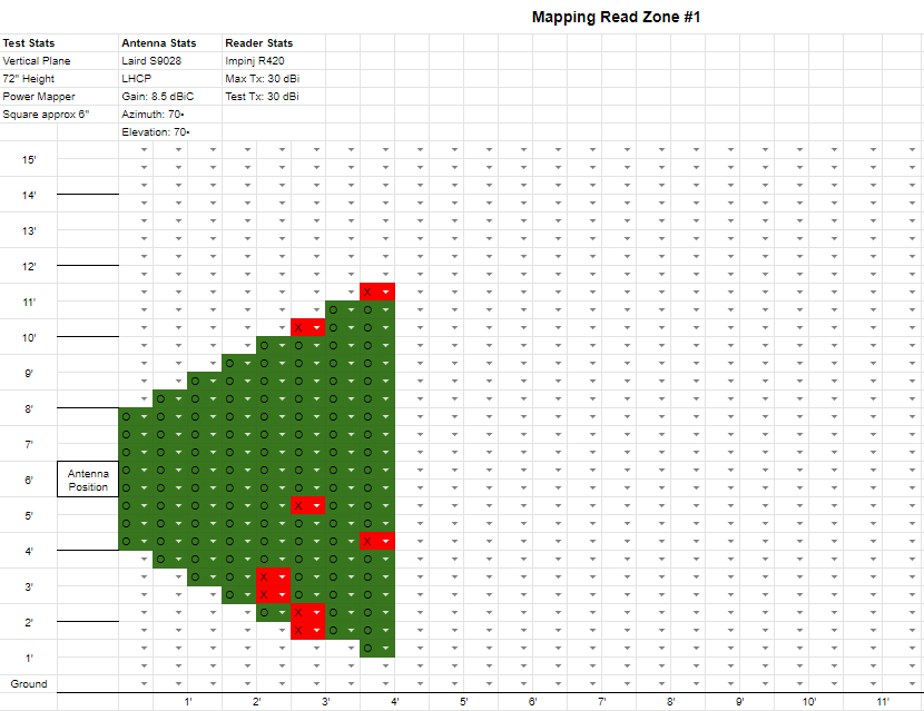
COMING SOON - Want to know when this and other configurable resources are available for download? Subscribe to the blog via the pop-up to be the first to access these read zone mapping resources.
If specifics are needed, use a spreadsheet that allows you to denote the power received via the RFID Power Mapper instead of a simple ‘X’ or ‘O’. Denoting the power could be important later in an application where certain RSSI (Received Signal Strength Indicator) values are critical to the success of the application. Below is an example of creating a read zone map with RSSI values.
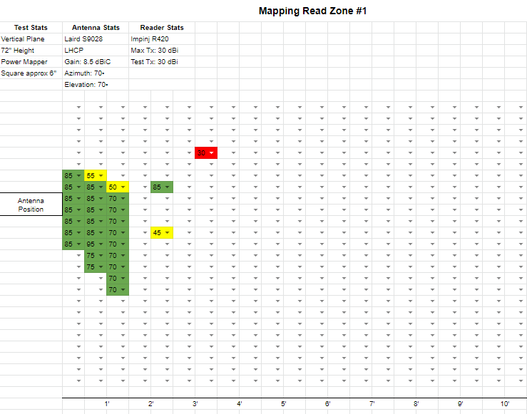
RSSI values typically range from -30 (extremely weak signal) to -85 (very strong signal). Want to know when this and other configurable resources are available for download? Subscribe to the blog via the pop-up to be the first to access these read zone mapping resources.
In these three examples of read zone mapping, the random occurrences of receiving no power are where the instances of destructive interference are located. These are due to multipath effects and can range from reflection off metallic surfaces to absorption from materials like carbon loaded foam. If there is an instance of multipath that is causing problems in your read zone, try to look at the surrounding environment and identify possible impacts from RF unfriendly materials.
Read more about these reactions in our article - “Understanding and Planning for RFID Multipath Environments.”
RFID Tags in Read Zones - Getting the Best Read Rates
Once a read zone is mapped and is better understood, it is important to take a look at the other side of the equation - the RFID tags. There are a few concepts that can be used to ensure that an RFID tagged item is setup for success in the RFID read zone.
The first, and most well-known strategy makes up the acronym SOAP - tag size, orientation, angle, and placement.
Size - a tag’s size usually correlates with its read range. The bigger the tag, the longer the read range.
Orientation - Tag orientation relative to the antenna matters. Try rotating the face of the tag on a flat surface to see which orientation produces the best read range.
Angle - The steeper the angle of the tag face relative to the antenna, the shorter the read range. When possible, ensure the front of the tag directly faces the antenna.
Placement - Test readability in a variety of spots on the item to find the “sweet spot” that generates the best reads. Also, when mounting on metal, be sure to use a metal-mount tag.
Read more about Tag SOAP in our article -
“6 Factors That Affect Read Range.”
To get a deeper understanding of tag orientation and angle, below are three ways to look at tag positioning: Pitch, Yaw, and Roll.
Pitch - is when the tag rotates along the x-axis.
Yaw - is when the tag rotates along the y-axis.
Roll - is when the tag rotates along the z-axis.
Read more about Pitch, Yaw, and Roll in our article -
“Pitch, Yaw, and Roll – Positioning RFID Tags”
Other important concepts to think about form a tag perspective are tag height in relation to antenna height and antenna polarization.
Tag Height - The tag height and antenna height should be about the same in order to get the best read range. Depending on the mapped read zone, the tag height can vary according to the read zone area, but it is best to try to have all tags at a consistent height.
Antenna Polarization - Antenna polarization is important if your RFID system has or will have a linearly polarized antenna. If the antenna is linear, the orientation of the tag on the z-axis, also called the Roll, will be critical in order to match up the tag antenna and system antenna.
Read more about Antenna Polarization in our article -
“Circular Polarization vs. Linear Polarization – Which is the Right RFID Antenna.”
RF Blocking and Reflective Materials
Read zones can be shaped and affected by adding RF absorbing and RF reflecting materials, such as foam or metal, respectively. Some applications benefit from using a contained read zone in a box or vessel because:
1. The application would benefit from introducing reflection and constructive interference, or
2. To mitigate stray reads in the read area, or a nearby read area
For example, containing a read zone inside a metal box, similar to a Faraday cage, allows the RFID system to capture more RFID tag reads due to the metal reflecting RF waves and creating multiple angles thereby increasing the read probability or accuracy that wasn’t available previously. To visualize this, think of a laser in a metal box. Without the metal box, the laser has one specific trajectory, but once the box is introduced, the laser’s reflected path is now able to reach certain places within the box that it wasn’t able to reach previously.
Using RF absorbing materials, such as foam, creates a dampening effect, which helps t contain the read zone. This dampening effect can help an RFID application if several other read zones are nearby, or if tag reads are being picked up in unwanted areas due to multipath. The RF absorbing materials essentially absorb the unwanted RF energy.
Conclusion
All of the concepts above can help you get a better understanding of your RFID System’s read zone and how to best setup hardware and tags for success. For more information on RFID systems and best practices, don’t hesitate to contact us or comment below!
To read more about RFID system best practices, checkout the links below!