What is RTLS? | An Introduction to Real-Time Location Systems
- What Is RTLS?
- RTLS Coverage Options
- What technology can be used for RTLS?
- Received Data & Granulation
What Does RTLS Stand For?
RTLS stands for Real Time Location Systems and refers to any system that accurately determines an item or person’s location. RTLS is not a specific type of system or technology, but rather is a goal that can be accomplished with a variety of systems for locating and managing assets. An important aspect of RTLS is the time at which assets are tracked, and this data can be used in different ways depending on the application. For example, some applications only need timestamps when an asset passes through an area, while other RTLS applications require much more granular visibility, and require that time data be updated constantly. An ideal Real Time Location System can accurately locate, track, and manage assets, inventory, or people and help companies to make knowledgeable decisions based on collected location data.
RTLS is used across many industries with specific applications like employee tracking and high-value asset tracking. These applications can be found in manufacturing and mining industries but are most prominent in the healthcare industry.
PARTS of an RTLS System
All RTLS applications will consist of a few basic components: a transponder, a receiver, and software to interpret the data from each. The complexity of the system, chosen technology, and scope of the application will determine the amount of hardware and software required to create the ideal RTLS.
Each technology used for RTLS utilizes its own terminology. Below are broad terms to help generally understand the items and their roles in a system:
Transponders
A transponder attaches to an item or person in order to uniquely identify that item or person. A transponder typically receives a signal from a receiver and responds back with its unique ID, but it can also send the initial signal if it contains an internal power source.
Depending on the type of technology and application goal, transponders can be:
- Radio-Frequency Identification (RFID) Tags
- Bluetooth Beacons
- Smart Devices
- Wi-Fi Tags
- Global Navigation Satellite System (GNSS)/Global Positioning System (GPS) Tags
- Ultrasound Tags
- Infrared Tags
- Smart Devices (Depending on the Mode)
Receivers
A receiver is a piece of hardware with a power source connected to a network that sends and receives signals from transponders. The receiver then forwards the collected data to back-end host computers or databases. In some systems, receivers can be existing infrastructure, but in others, receivers must be purchased and incorporated into the application environment.
Depending on the type of technology and application goal, hardware can be:
- Readers
- Location Sensors
- Access Points
- Receivers
- Beacons (Depending on the Mode)
- Smart Devices (Depending on the Mode)
Software
The software in these systems can vary in complexity, from a simple software integrated on the receiver hardware, to multiple software instances, like a location engine software, middleware, and application software on a host computer. Software can be combined to create the desired functionality of the system. Three main types are used in RTLS applications:
- Firmware - software that resides on the hardware
- Software or application software - software that resides on the back-end computer or server
- Middleware - used to connect firmware and application software
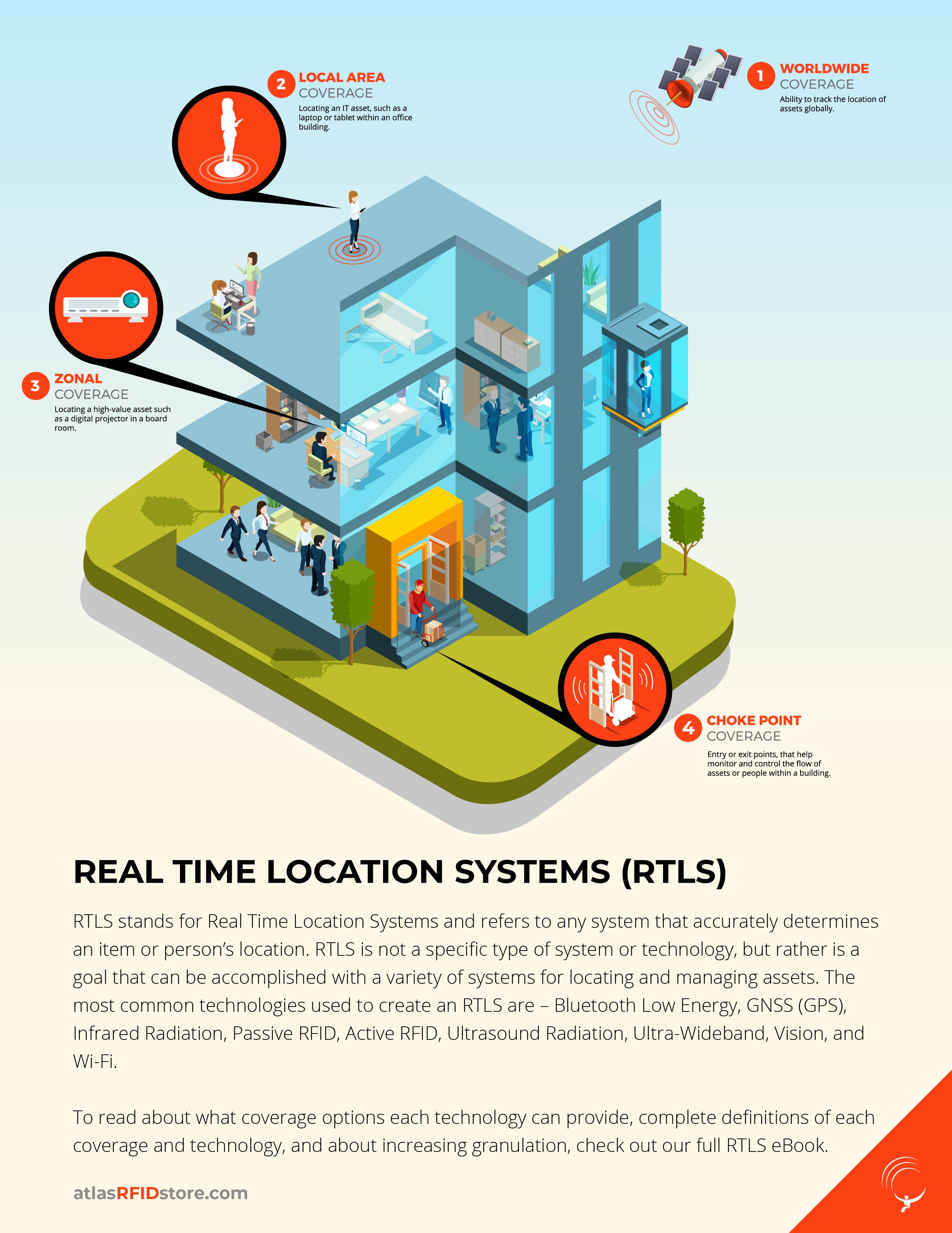
RTLS Coverage Options
RTLS capabilities and read ranges vary from one technology and setup to another. For example, the system with the longest read range, GNSS (GPS), can provide an item’s real-time location anywhere in the world because the receivers are satellites orbiting the Earth. Other technologies with shorter read ranges like UHF Passive RFID can provide location within a building or zone. Below are different coverage levels achievable using RTLS. Note that increased granularity can be achieved with each of these coverage options depending on the technology chosen, the number of receivers and/or tags, and/or the type of positioning method chosen.
![]()
Wide Area Coverage - Generally refers to locating an item or person on a global scale using global coordinates.
Application Example: Locating cargo containers traveling across ocean or land with valuable machinery inside.
![]()
Local Area Coverage - Generally refers to locating an item or person within a building or facility that is on the same network.
Application Example: Locating an IT asset within a company’s building.
![]()
Zonal Coverage - Generally refers to locating an item or person within a set zone (i.e. room, office in a larger area) by setting up hardware at intervals based on read range and read obstacles.
Application Example: Locating a high-value oxygen tank inside a hospital.
![]()
Choke Points - Generally refers to areas that items or people must go through in order to conduct normal business (i.e. doorways, hallways, entrances/exits). Typically smaller in width in order to accommodate read ranges of certain technologies.
Application Example: Determining what area in a warehouse a pallet is being stored with manufactured products.
What technology can be used for RTLS?
When implementing an RTLS, it is important to select the right technology to fit the application’s needs. This article will focus on the most prevalent technologies used to accomplish successful RTLS applications.
Bluetooth Low Energy
Bluetooth Low Energy, or BLE, is used for RTLS capabilities. BLE tags, also called beacons, can be set to constantly broadcast a signal to the surrounding area. These signals can be picked up by any device that has Bluetooth capabilities, like Bluetooth receivers, other BLE tags and Beacons, or smart devices. An RTLS using BLE can be setup with either Beacons or Bluetooth receivers mounted in fixed locations and assigned specific coordinates. For example, when a BLE transponder enters a receiver’s zone, the transponder will communicate its location to the receiver. This response can then be sent to a BLE Gateway via a Wi-Fi signal, and the BLE Gateway records that data and sends it to a host computer or networked/cloud database.
Base-Level System Parts:
- BLE Tags/Beacons - Powered by Receiver’s Signal, Battery, or Smart Devices
- BLE Receivers/Bluetooth Access Points
- BLE Gateway
- Host Computer or Networked/Cloud Database
Best For: Zonal Coverage; Choke Point Coverage
Pros: Bluetooth Devices can be used; Standardized Technology; Telemetry Options
Cons: High Tag Cost; High Amount of Tags Needed
GNSS/GPS
GNSS, or Global Navigation Satellite System, is a satellite system that provides coverage over a wide area on a global scale. GNSS is commonly referred to as GPS because the United States’ NAVSTAR GPS satellite system is the most well-known satellite system for GNSS navigating or locating. Using GNSS for RTLS can be accomplished by tagging assets with GNSS tags that also have Wi-Fi, Bluetooth, or Cellular connectivity. Satellites orbiting the Earth continually send out radio waves modulated with their orbit location information and a time-stamp from a precise atomic clock. The GNSS tag or smart device receives these signals from at least 3 satellites and uses that data to compute the tag’s own location in terms of global coordinates. Those coordinates can then be sent to a host computer or networked/cloud database using the secondary technology on the tag, such as Wi-Fi.
Base-Level System Parts:
- GNSS Tags - Powered by Battery; Smart Devices
- Receivers - GNSS Receivers; Smart Devices
- Host Computer or Networked/Cloud Database
Best For: Wide Area Coverage, Local Area Coverage
Pros: Only Tag Costs; Telemetry Options
Cons: Outdoor Tracking only; High Tag Cost
Infrared Radiation
As the name implies, infrared radiation is found on the electromagnetic spectrum below what the human eye can detect as visible light. This lower frequency presents certain limitations, like the inability for IR waves to travel through solid objects like walls. However, this is perfect for covering individual zones and rooms. Infrared tags can be paired with another technology, such as Wi-Fi or Bluetooth, to provide more accuracy in large areas. Infrared tags send out signals modulated with their unique ID into the room or zone using a small battery. Infrared receivers are mounted in fixed locations, pick up the tag’s signal and unique ID, and forward the data via Wi-Fi or LAN connection to a host computer or networked/cloud database.
Base-Level System Parts:
- Infrared Tags - Powered by Battery
- Receivers - Infrared Receivers
- Host Computer or Networked/Cloud Database
Best For: Zonal Coverage
Pros: High Accuracy; Low Cost; Perfect for Room-Level Accuracy
Cons: Low Range; Dense Items cause Multipath Issues; No Standards
Passive RFID
Passive Ultra-High Frequency (UHF) RFID can be used in different ways to create RTLS efficiency. The simplest way to accomplish this is by covering choke points at entrances/exits to rooms or buildings. By mounting the hardware (i.e. RFID Readers and Antennas) at choke point locations and tagging assets with RFID tags, item locations at specific read times can be clearly available. Zonal coverage can be achieved by dividing up rooms or areas and strategically placing RFID antennas to send signals to the tagged assets in the area. In addition, like most other RTLS technology, a more granular approach can be taken in zones or rooms by mounting antennas every few meters and using trilateration to determine the exact location of the tagged asset.
Base-Level System Parts:
- RFID Tags - Powered by transmitted Receiver Signal
- Receivers - RFID Readers and RFID Antennas
- Host Computer or Networked/Cloud Database
Best For: Choke Point Coverage; Zonal Coverage; Local Area Coverage
Pros: Less Expensive Tags; Setup Options; Standardized Technology
Cons: Metal & Water Interference; Multipath
Active RFID
Active UHF RFID is typically used for RTLS in large, outdoor environments. Depending on the setup, active RFID can have a large read range of hundreds of meters. Instead of waiting for the reader to send a signal to power the tags like Passive RFID, Active RFID tags contain a battery to enable continuous signal broadcasting. The interval time between tag broadcasts can be set based on the manufacturer’s options. The tags typically send their unique ID along with any additional information that has been programmed, such as indicators like signal strength or environmental measurements. Fixed readers, spaced accordingly, or mobile readers receive this information and take note of location indicators, allowing them to give detailed locations to the host computer or networked/cloud database.
Base-Level System Parts:
- RFID Tags - Powered by Battery
- Receivers - RFID Readers and RFID Antennas
- Host Computer or Networked/Cloud Database
Best For: Local Area Coverage; Zonal Coverage
Pros: Rugged tags for outdoor use; Telemetry Options
Cons: Expensive tags and hardware; No standards for Active RFID
Ultrasound Radiation
Ultrasound Radiation has similar limitations as Infrared Radiation because the signals cannot penetrate walls or other dense objects, making it perfect for room-level positioning. The difference between the two is that Ultrasound signals are acoustic signals that must be picked up by receivers with microphones tuned in to the Ultrasound Frequency band. In an Ultrasound system, tags with small batteries send their unique ID signals to receivers in the room. Once receivers hear the signals, a data file is created based on the unique ID transmitted in the signal, and that data is sent to the host computer or networked/cloud database.
Base-Level System Parts:
- Ultrasound Tags - Powered by Battery
- Ultrasound Receivers - Microphone Receivers
- Host Computer or Networked/Cloud Database
Best For: Zonal Coverage
Pros: High Accuracy; Perfect for Room-Level Accuracy
Cons: Low Range; Dense Items like Walls cause Multipath Issues; No Standards
Ultra-Wideband
Ultra-Wideband Technology, or UWB, functions similarly to Active RFID in that the tag is continuously sending out RF energy into the environment for receivers to pick up. In larger environments with many tags, receivers are placed at larger intervals with sub-receivers in between to improve accuracy. The signals from the tags are extremely short and obtain the unique ID of the tag. Receivers forward that information to the host computer or networked/cloud database where software calculates/computes the location based on the positioning indicators. UWB is highly accurate on a room-level and zone-level basis and can calculate location within a few centimeters due to its short, narrow transmissions.
Base-Level System Parts:
- UWB Tags - Powered by Battery
- UWB Receivers - Receivers; Sub-Receivers
- Host Computer or Networked/Cloud Database
Best For: Zonal Coverage
Pros: High Accuracy; Able to mitigate metal & water interference; Doesn’t interfere with other RF systems
Cons: Cabling may be required; High cost based on number of receivers and sub-receivers
Vision
Systems can be set up for RTLS capabilities with images and cameras to monitor items and people. Vision-based systems use high-end cameras to detect and recognize item locations. Outfitted with additional technology, like Wi-Fi or Bluetooth, the cameras can send those images or image data and timestamps to host computers or networked/cloud databases. Vision-based systems can provide varying types of accuracy depending on the image quality of the camera, the lighting and visibility in the environment, and the distance between the camera and the item/person.
Base-Level System Parts:
- Video Cameras Powered by Battery or Outlet
- Host Computer or Networked/Cloud Database
Best For: Zonal Coverage; Local Area Coverage
Pros: No tags needed; Hardware is easy to deploy
Cons: High Infrastructure Cost; If all items are visually identical, the system would need another type of technology to provide a unique ID
Wi-Fi
A location system based on Wi-Fi is popular because pre-existing Wi-Fi access points can be leveraged without many additional hardware costs. Wi-Fi tags or smart devices with internal Wi-Fi Radios can send signals to Wi-Fi access points in the area, or vice-versa. Depending on the number of Wi-Fi access points, several positioning indicators can be used to calculate distance from the access points. Like other RTLS technologies, if multiple access points receive the signal, the item location can be more accurately given using trilateration once the data is sent to the host computer or networked/cloud database.
Base-Level System Parts:
- Video Cameras Powered by Battery or Outlet
- Host Computer or Networked/Cloud Database
Best For: Local Area Coverage; Zonal Coverage
Pros: Leverage existing Wi-Fi infrastructure; Several Setup Options; Smart Devices can act as Tags; Standardized
Cons: High Tag Cost; Varying Degrees of Accuracy Based on Hardware and Environment; Increased Wi-Fi Traffic
*Of note, there are other technologies out there that are not covered in this RTLS technology section for several reasons, including complexity, out-of-date technology, and lack of current application citation.
Received Data & Granulation
Most technologies used for RTLS send their unique ID back to the receiver, and in applications that simply need relative zonal coverage, or choke point coverage, that information is sufficient to send back to the host computer or database. In other applications, simply sending back the tag’s unique ID is not granular enough to answer where the item or person is. For example, to provide precise location coordinates, GNSS automatically provides granularity in two ways:
- GNSS tags will not report their location without receiving at least three satellite signals. This is called trilateration or multilateration.
- Satellites send their signal back with additional data besides the Satellite ID: precise orbit location and a timestamp. These can be called positioning or location indicators.
If the coverage area is too big or there are not enough receivers or tags to provide granularity, position indicators and/or multilateration can be put in place to provide more accuracy.
First: Trilateration
In order to accomplish RTLS in one of the coverage levels mentioned above, the correct technology in combination with the correct positioning method must be successfully used to ensure accuracy and precision.
All technologies can give a more accurate picture of where the item or person is located if more than one receiver captures a tag’s signal. If multiple receivers capture a tag’s data, position indicators can be compared to create a more accurate picture of the location.
Trilateration - Trilateration is a common method for calculating positions within the known coordinates of three fixed points (typically receivers) and either using their fixed locations, or other reported indicators, to narrow down the location of the object.
Triangulation - Commonly mistaken as trilateration, triangulation is the calculation of an item’s position using known distances between two or three fixed points (typically receivers) and the angles of each known point to the item’s location.
Multilateration - Multilateration utilizes the same calculations and data as trilateration, but with more fixed location points (receivers). The addition of more than three location points further increases the accuracy and granularity of an object’s location.
Second: What are Location Indicators and How Are They Used?
Location indicators are measurements like time, angle, or signal strength that can be either calculated by the receiver or captured by the tag to provide a more accurate look into an item’s position. These indicators can be collected and used in a few different ways through specialized algorithms created by software. Below are a few of the most common methods or algorithms to determine location organized by location indicator:
Time
Time of Arrival Method or TOA
In this method, the tag documents the start time of the signal (t1) and then documents the exact time the signal was received at the receivers (t2) and uses software to calculate the elapsed time (t2 - t1). The tag then sends that data along with the tag’s unique ID to the host computer/network. This method can only be used if the tag (or smart device) has an internal clock and is synchronized with internal clocks within the receivers. This method can provide a more accurate location when used with three to four receivers and trilateration.
Time Distance of Arrival Method or TDOA
This method doesn’t require the start time of the signal from the tag (tag internal clock not needed), but instead notes the received signal time and the unique ID and sends that information to the host computer/network. This method, also called TDOA, relies upon many tags and location sensors in the field , as well as heavy processing power for the application software or middleware. This method provides locations based on the received signal time from each Unique Tag ID and uses multi- or trilateration to provide precise locations.
Time of Flight Method or TOF
This method is comparable to the TOA method because both use the time a signal is sent (t1) and the time it was received (t2) to calculate elapsed time to send to the host computer/network. The difference with the Time of Flight (TOF) method is that the originating signal is sent from the reader/receiver, so the timestamp of the signal is either predetermined and known, or it is modulated into the signal to the tag. The tag then records the time that signal arrives, demodulates the signal (if necessary), and calculates the time of flight between the receiver and tag with (t2 - t1). Similar to the TOA method, the TOF method requires that the tag have an internal clock.
Round Trip Time Method or RTT
This method is comparable to the TOA and TOF methods because all three use the time a signal is sent (t1) and the time it was received (t2) to calculate elapsed time to send to the host computer/network. The difference with the RTT method is that it calculates the round-trip time. The originating signal is sent from the reader/receiver, and the time that the receiver sends the signal is recorded. It then sends the time the signal was received back from the tag, the signal’s originating time, along with the tag’s unique ID, back to the host computer/network. Similar to the TDOA method, the TOF method does not require the tags to have an internal clock.
Angle
Angle of Arrival Method or AOA
This method is regularly used with two or more receivers and knowledge of each receiver’s position, angle, and orientation. Each receiver must also have a fixed reference direction, like north, south, east, or west. The receivers both receive the tag’s signal and calculate the angle in reference to the known fixed reference direction. They then send this information back to the host computer/network that uses the known position of each of the receivers to accurately calculate the position of the tag. The more receivers that receive the tag’s angle in relation to the fixed direction, the more precise the item’s location.
Signal Strength
Received Signal Strength Indicator (RSSI) Method
This method is used commonly with RFID and other related technologies. The RSSI value is the signal strength of the tag’s return signal computed by the Receiver. The RSSI value can also be calculated for each part of the signal, from Receiver to Tag and Tag to Receiver, if the Tag has onboard computing abilities.
To learn more about time indicators – click here.
RTLS example with trilateration and position indicators
In a warehouse, a Company X stores high value equipment that has been returned for service or replacement. Each piece of equipment ranges in cost from $1,000 – $10,000, and some pieces are manually calibrated for specific customers. Because this is Company X’s only servicing warehouse in North America, all problematic equipment is sent to this location, meaning that at one time, Company X might have hundreds of assets on site.
Each piece of equipment must be tagged upon receipt and logged with information like Customer Name, Type of Equipment, Equipment Use, Problem/Equipment Issue, Received Date, etc. Company X decided to use Passive RFID because the warehouse is already set up in zones, and the affordable price of disposable tags.
Company X’s warehouse is divided in half, with 5,000 sq. feet a work shop, and the other 5,000 sq. feet are shelves for defective equipment. Company X already has 5 ‘Zones,’ each 1,000 sq. feet square and roughly 32 feet in length and width. Because they want to save money, Company X decides to only use two, high-powered RFID readers per zone in conjunction with an antenna hub to power 13 RFID antennas each, totaling 26 antennas that are evenly spread throughout the read zone. In order to give Company X a more granular look into the location of the assets, the readers are programmed to send each tag’s unique ID and the RSSI measurement to the cloud database. Because the antennas overlap in read zones, at least three reads and the corresponding RSSI values are required to give accurate location. Once the tag is queried, three antennas read the tag’s unique ID and send the RSSI value to the database. The software receives that information and, with the help of a custom algorithm, provides the location in inches to the technicians.
The technicians can then go to that specific zone and area, according to the application software on their handheld PCs, and are able to locate the product to be serviced.
Want to Learn More?
atlasRFIDstore has been providing RFID infrastructure, solutions, and education since 2008 to companies around the world. Check out some of our most popular eBooks below to learn RFID Basics, Types of RFID, and information on individual RFID infrastructure like RFID Readers and RFID Tags. If you have any questions, feel free to contact us.
*Malik, Ajay. RTLS For Dummies. 2009 John Wiley and Sons.
*Wikipedia. Subject: RTLS, Trilateration, Multilateration, Time Indicators