RF Physics: How Does Energy Flow in an RFID System?
RF Physics & RFID: A Brief Overview
RFID systems, like all systems involving energy, are governed by the laws of physics. Physics is the study of matter and its motion through space and time, along with related concepts such as energy and force. To delve deeper, RFID systems also are subjected to fundamental electromagnetic principles. These principles speak to the transfer of energy and the electromagnetic spectrum, are defined in Faraday’s Law of Electromagnetic induction and Lenz’s Law. In addition, governments and military departments regulate the use of the electromagnetic spectrum (frequency and power of transmission) in various parts of the world, which leads to different standards and regulations governing RFID systems.
Every aspect of an RFID system is designed using the laws and standards as stated above in order to successfully exchange information using an electromagnetic field and modulated energy. Each part of the process – reader to cable, cable to antenna, and antenna to tag (and back) ensures effective energy transfer between the segments.
Each step in the energy flow process of a typical UHF RFID system is simply defined below.
Energy Flow: Reader to Cable
Energy flows out of an electrical outlet as AC power (Alternating Current power) which means electrons periodically reverse directions as they are traveling, enabling the energy to be transmitted longer distances relative to DC power (Direct Current power). A typical RFID reader power supply included with an RFID reader is an AC to DC power converter, changing the alternating current from the outlet to a direct current (which is more suitable for the reader electronics).
Next, the direct current runs through an Oscillator and Phase Locked Loop (PLL) module which then converts the direct current from the power supply to an alternating current at a variable frequency. The variable frequency is determined by a frequency hopping algorithm inside the RFID reader, which is based upon the frequency range set during the manufacturing stage.
For example, in the United States, each reader is required to employ a frequency hopping algorithm due to regulations stating that a single reader cannot transmit on a specific frequency for more than 400 milliseconds or 0.4 seconds in order to prevent crowding specific frequencies. While using an RF reader set for the US FCC frequency range, the reader will ‘hop’ every 0.4 seconds in a predetermined pattern such as 902.5 MHz (0.4 s), 903.5 MHz (0.4 s), 927 MHz (0.4 s), and so on. If a reader were to stay on one frequency for longer than 0.4 seconds there could be interference between neighboring radios.
After the value of the variable frequency has been set, the resulting signal is then amplified using the RF amplifier and modulated by the information that the reader is attempting to send to the RFID tag. An RF amplifier determines the power of the signal to be transmitted by the RFID reader (i.e. its transmit power) and amplifies the RF signal to that desired power level. According to US FCC regulations, the power signal sent from the reader cannot exceed 1 watt (30 dBm). However, because the power from the antenna includes attenuation due to cable loss, some RFID readers are able to transmit power levels of over 30 dBm (for example, 31.5 dBm). The attenuation of the cable then negates the extra transmit power enabling the reader not to be in violation of FCC standard 15.247. When using reader transmit power levels of > 30 dBm, operators need to ensure that the cable being used will provide the required attenuation so that the power input into the antenna does not exceed 1 Watt. (Check out the GS1 document, for more specifics on regulations for UHF RFID in other countries.)
The amplified signal is then passed through an RF Bandpass Filter that eliminates any additional frequencies that are outside of the allowed transmission band. After passing through the Bandpass Filter, the signal is then output to the antenna port and, subsequently, to the coaxial cable through a directional coupler.
Energy Flow: Cable to Antenna
The signal is then conducted through a coaxial cable into the RFID Antenna. Of note, power is lost in this process due to the attenuation of the signal as it travels along the cable. The amount of power lost depends on the length of the cable and its insulation rating. Lower loss cables are usually thicker and shorter in length. [Read more about Getting the Most from Your RFID Cable.]
When the coaxial cable is properly connected to the antenna port, the center pin of the cable connector is connected to the radiating element of the antenna. The signal (or AC current) flows from the center pin, to the radiating element, and then through the medium to the grounding element (see diagram below). The radiating element in conjunction with the ground plane focuses the energy based on the gain parameters of the antenna in order to build the electromagnetic field.
When the electromagnetic field is built, the radiating element releases the electromagnetic waves, which propagate out from the antenna. The shape and form of the radiated energy is called the radiation pattern of the antenna.
The beamwidth of the antenna can be calculated from the radiation pattern of the antenna. Beamwidth is the angle between the half power points of the main lobe of the radiation pattern. The radiation pattern, beamwidth, and gain are all affected by the size of the grounding plate as well as the size of the radiating plate.
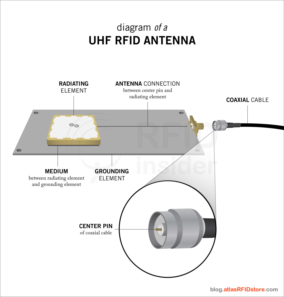
*The diagram above represents the basic components required for any UHF RFID antenna. Depending on the antenna specifications, the size and shape of the various sub-components may change.
Energy Flow: Antenna to Tag (And Back)
The propagated waves travel in space to a distance vertically and horizontally based on the specific gain and beamwidth parameters of the antenna.
The RFID tags in the field receive the energy, or RF waves, using their own antennas. The energy received travels through the RFID tag's antenna and a portion of it is used to activate the chip (i.e. the Integrated Circuit, or IC) and prepare for transmission of data based on commands received from the RFID reader.
When the chip is turned on, it modulates the energy with the information stored in the tag (pertinent to the reader’s request) and "reflects" the remaining energy back. This information could be EPC memory, User Memory, or anything programmed on the tag. This reflection of energy back to the antenna is known as backscatter radiation.
The backscatter radiation travels through the air, into the RFID antenna's field, and back through the coaxial cable into the antenna port on the RFID reader. The directional coupler picks up the received signal and passes it through the bandpass filter, a mixer, and a baseband amplifier to a decoding circuit to recover the tag's information.
Conclusion
If you have any questions about the physics of an RFID system, please comment below or contact us for more information.
If you would like to learn more about all things RFID, check out our website or our YouTube channel.