A Guide to Cables, Connectors, and Adapters
Contents
- What do Cables and Cable Connectors Do?
- Components of Coaxial Cables
- Determining Cable Loss
- Size Comparison
- Coaxial Cable Connectors
- The Threading (Female or Male)
- The Center Pin (RP)
- Connections
- Connector Chart
- Adapters vs. Cables
What Do Cables & Cable Connectors Do?
Coaxial cables provide the essential link between an RFID reader and an antenna. They can also be used to connect auxiliary devices like antenna hubs and multiplexers in certain applications. Coaxial cables are energy conductors consisting of a copper core that is insulated by both metal and rubber. The energy generated by the RFID reader is sent via the antenna port of the reader, into the first connector, through the cable, out the other connector, and into the antenna. The better insulated the cable is, the less energy lost during the process. [For a more detailed look at RFID energy flow in a system read: RF Physics: How Does Energy Flow in an RFID System].
Antenna cables terminate at both ends in a connector; but, connectors, as well as adapters, can also be sold separately.
Components of Coaxial Cables
Cables have one job – to transfer energy; but, just as important, cables must be properly built to combat potential energy loss. Energy loss happens in every system; the key here is to understand how it is lost from a cable in order to fight it.
Three components make up a coaxial cable, and are important to understand in order to select the correct cable for an application.
Length – The longer the cable, the farther the energy has to travel. No antenna cable is perfectly insulated; so, the farther the energy travels, the more energy it will lose. In some applications, the reader is farther from the antenna due to the nature of the application. If a long cable must be used, it is important to use the appropriate level of insulation required to combat loss.
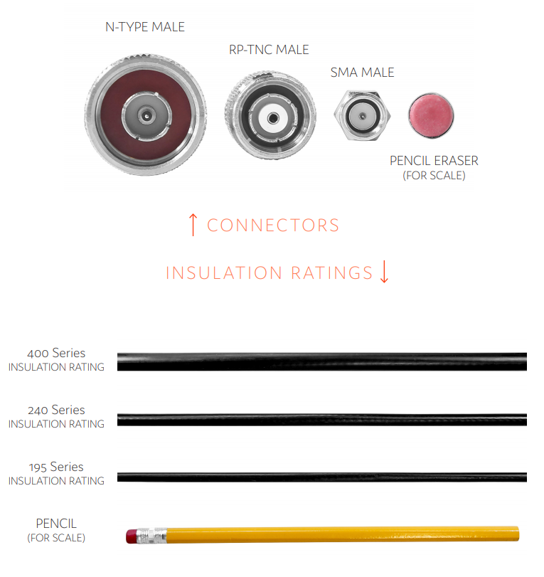
Insulation Rating – The higher the insulation rating, the thicker and more protected the cable. The most common ratings used with UHF coaxial cables are 195 series, 240 series, and 400 series. The downside to a thicker, more insulated cable is that the cable is less pliable and could be difficult to position in a tight space.
Connectors – Connectors are located at both ends of a cable, and their type is determined by the connectors on the reader and antenna being used in the application. Later, this guide will walk through what types of connectors are compatible with each other.
Determining Cable Loss
Cable loss is the amount of power lost from the cable and is determined by the insulation rating and length of the cable. For applications that need a system running at maximum power to provide long read range or for tracking at high speeds - the reader’s transmit power, cable loss, and antenna gain will play key roles. Below is a chart documenting cable loss by length for each insulation rating. This chart shows the correlation between the two so that, if the cable must be lengthened, a higher insulation rating can be used to offset the loss.

*Of note, because power is being measured on the decibel scale, for every 3 dB reduction, the power is cut in half. A reduction of 6 dB would be only 25% of the original power setting, and so on. Likewise, for every 3 dB increase, the transmitted power doubles.
If an application isn’t getting the desired read range, transmit power on the reader and cable loss can easily be calculated and adjusted. If the application is losing too much energy from the cable, consider decreasing the length and/or increasing the insulation rating to ensure more energy is received by the antenna.
To easily calculate the amount of power that the RFID antenna is receiving, see the equation below.
Transmit Power (dBm) - Cable Loss (dB) = Antenna Input
Additionally, if the power entering the antenna isn’t quite enough, a higher gain antenna can be used. To calculate the total system output of power at the antenna, the following equation can be used:
Transmit Power (dBm) - Cable Loss (dB) + Antenna Gain (dB) = System Output
30 dBm - 3 dB + 6 dB = 33 dBm
Please note that most regions limit the total power output from the point of the antenna. For example, FCC regulations limit the total power output to 4 watts or 36 dBm. Be sure to check the regulations for your region to ensure your system is in compliance.
[For more tips on improving your RFID system's read range, read
Size Comparisons
Coaxial Cable Connections
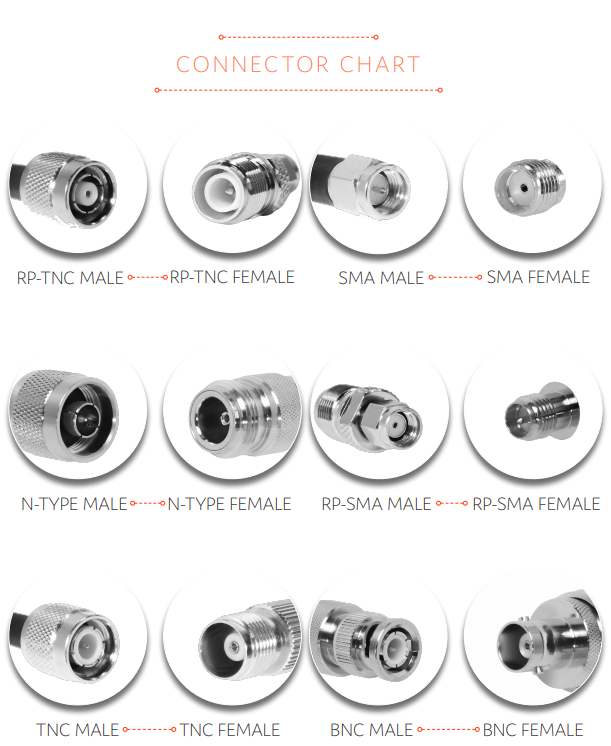
Connecting a cable from the antenna to the reader in an RFID system isn’t difficult – but purchasing the correct cable that will join the hardware together can be a tedious task. Quite a few types of cable connectors can be used, and each one is dictated by the connectors on the hardware. The chart below walks through the most popular types of coaxial connectors with a little information about each.

The Threading (Male vs. Female)
On a coaxial cable connector or adapter, the threading is either on the outside of the connector in plain view, or on the inside of the connector. Two terms are used for each of these types of connectors:

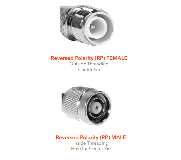
The Center Pin (Normal vs. Reverse Polarity)
The center pin of a coaxial connector is the component that conducts the RF energy and is one key to identifying what type it is and with what it is compatible. There are two options when it comes to the center pin of a connector, normal polarity or reverse polarity.
Female/Jack - A normal female/jack connector has the threading on the outside and a hole in the center to receive the male/plug's center pin.
Male/Plug - A male/plug connector has the threading on the inside and a metal center pin to insert into a female/jack connector.
Key takeaway: Normal polarity = center pin is in the MALE connector.

Female/Jack - A reverse-polarity female/jack connector still has the threading on the outside, but, because the polarity has been reversed, the center pin is on the inside of this connector.
Male/Plug - A reverse-polarity male/plug connector still has the threading on the inside, but because the polarity as been reversed, the hole is on the inside of this connector.
Key takeaway: Reverse polarity = center pin is in the FEMALE connector.
Connections
Ensuring two connectors will properly join and work as expected can sometimes be a confusing and tedious task. For example, if an RFID reader has an RP-TNC Female connector, should it connect to a RP-TNC Male, a TNC Female, or a TNC Male? These four types have similar names and sizes, and ordering the incorrect type can add several days’ worth of delay to a project. Below are a few rules to go by, as well as a visual connection guide to simplify the process.
Rule #1 – Similar types connect.
Example: TNC connects to a TNC; SMA
Rule #2 – Similar polarities connect.
Example: RP-SMA connects to an RP-SMA;; RP-TNC connects to an RP-TNC
Rule #3 – Opposite genders/threading types connect.
Example: SMA Male connects to an SMA Female, RP-TNC Male connects to an RP-TNC Female

An adapter is used to join any two coaxial connectors that would otherwise be incompatible. There are two scenarios where a coaxial adapter may be required:
- If one or both connectors on a cable is incompatible with the RFID reader or antenna.
Purchasing a cable with the incorrect connectors can happen easily; not only are some of them similarly named, but they appear similar in pictures as well.
- To save money when experimenting with different antennas and readers.
If an application is still in the testing phase, several different antennas and/or readers can be purchased for experimentation. Instead of purchasing several cables with different connectors to match each reader/antenna combination, one cable and a few different adapters can be purchased instead. This can save time and money during testing.
If you have any additional questions about if RFID is right for your application, or about connectors & adapters, don't hesitate to contact us.