
RFID Antenna Buyer's Guide: 9 Tactics for Choosing an RFID Antenna
Contents
- Introduction
- RFID Antenna Size
- RFID Antennas: Indoor or Outdoor
- RFID Antenna Form
- RFID Antenna Frequency Range
- RFID Energy Flow to an RFID Antenna
- Circular or Linear
- RFID Antennas Range: Far Field or Near Field
- What is RFID Antenna Gain
- RFID Antenna's Beam: Wide or Narrow Beamwidth
- What Direction do RFID Antennas Transmit?
- Worksheet: How to Choose an RFID Antenna
Introduction
In short, RFID Antennas take energy from an RFID reader and transmit it in the form of RF waves to RFID tags in the vicinity. If RFID Readers are the “brains” of an RFID system, RFID antennas are the arms because they actually transmit RF waves to the tags.
In addition to transmitting, antennas also receive the information sent from the tags so the reader can decode it. While antennas are usually described as “dumb devices” in an RFID system, there are many different types, each with distinguishing characteristics, which makes selecting the right antenna extremely important.
Before selecting an RFID antenna for a specific application, consider the information below about antenna types and options in order to make the right choice.
RFID Antenna Size
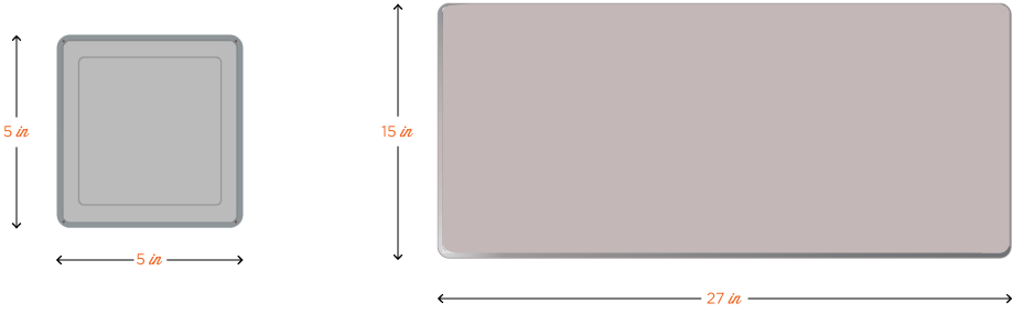
RFID Antennas range in size from smaller than a standard cell phone, to as large as a TV. The difference in size is usually indicative of the read range – the bigger the antenna, the higher the gain, the longer read range and vice versa. Some antennas, however, are exceptions to the rule because they were built for a specific application; one example is the large Impinj Guardwall antenna. Built for tightly controlled read spaces, the Guardwall antenna only has a gain of 6 dBi because it is designed to be mounted across from another Guardwall to create a small, accurate read zone.
Size constraints may also factor into the decision making process because some applications do not allow for much available space in the area where the antenna will be placed. Certain environments, like retail stores, may not have the space for a bulky 15 x 15-inch antenna, nor will such an antenna fit in aesthetically. Small antennas are optimal for item level reading and writing as well as for applications that require smaller read zones like conveyor belt reading and personnel access control applications.
Key takeaway: The size of the antenna should depend on the space available in the application environment. Also remember, generally the smaller the antenna, the shorter the read range.
RFID Antennas: Indoor or Outdoor
Because RFID applications can be implemented in almost any environment, each part of an RFID system must be reviewed or tested for ingress protection against water and dust. Just as most personal phones are not designed for use outside in a rain storm, most RFID technology is not either. All electronic devices are rated on ingress protection (IP) from dust and water, by the US IEC standard 60529 and the British standard EN 60529 ranging from IP 00 to IP 69.
The first digit in the IP rating can be between 0 – 6 and describes the level of protection against solids – like objects or dust. Zero specifies not protected at all against solid objects, and six specifies that the piece of equipment is completely protected from dust. The second digit in the IP rating can be between 0 – 9 and indicates the level of protection against liquids. Zero indicates not protected at all from any liquid, and 9 indicates protected from continuous immersion in liquids that the manufacturer deems safe for the product. IP69 exists and describes a product protected completely from dust and from high pressure liquid, and is the only IP rating that ends in a nine.
The antenna’s operating temperature range is not just important for extreme temperature applications; it also should be checked for outdoor or nonclimate controlled indoor applications. All RFID equipment has an operating temperature range that should be strictly followed, otherwise the equipment could work slowly, stop working, or react negatively to temperatures outside of the specified range.
For extreme temperature applications and/or low IP-rated equipment, solutions exist as a “work around” – for example, weatherproof enclosures and temperature-controlled enclosures.
Key takeaway: Outdoor, non-climate controlled indoor, and extreme temperature applications will require an antenna with a high IP rating and/or a wide operating temperature range.
RFID Antenna Form
RFID antennas can either be integrated within a reader as one device, or purchased separately as an external piece of hardware. Integrating a reader and antenna saves space and provides a more mobile system without worrying about lengthy cabling. Integrated reader antennas are also optimum for retail or desktop applications because they are usually compact, easy to use, and more visually appealing than two bulky external devices. External antennas, on the other hand, provide for many more options and flexibility within any given application.
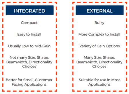
Key takeaway: Before purchasing a reader or antenna, decide if the application is small enough or customer facing where it would benefit from an integrated reader and antenna.
RFID Antenna Frequency Range
Just like RFID readers and RFID tags, RFID antennas are designed for use within specific frequency ranges. Without being tuned to a specific frequency range, antennas would not be able to transmit or receive information from either the reader or the tag. Most RFID antennas fall into one of the following operating regions:
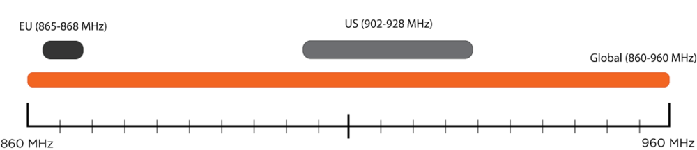
US or FCC (902 – 928 MHz)
EU or ETSI (865 – 868 MHz)
Global (860 – 960 MHz)
The Global operating region is a good “catch all” for applications that run in multiple countries, or for applications that will be tested in both the US and Europe. Otherwise, it is better to choose an antenna with a narrower frequency range; doing so will result in better performance and, all things being equal, a longer read range. Of note, all RFID equipment working together within any given system must be tuned to the same frequency range in order to communicate successfully.
In order to decide which frequency or operating region is appropriate for an application, double check the frequency guide provided by GS1 and ensure that all parts of the RFID system (tags, reader, and antenna) are all compliant within the country they are operating.
Key takeaway: If the system will be operating somewhere other than the US or Europe, double check the frequency guide for each country’s specific regulations. A global frequency range antenna is a good fall back if the exact regulations aren’t specified.
RFID Energy Flow to an RFID Antenna
 The way that energy flows through an RFID system is key to understanding RFID antennas and the role they play.
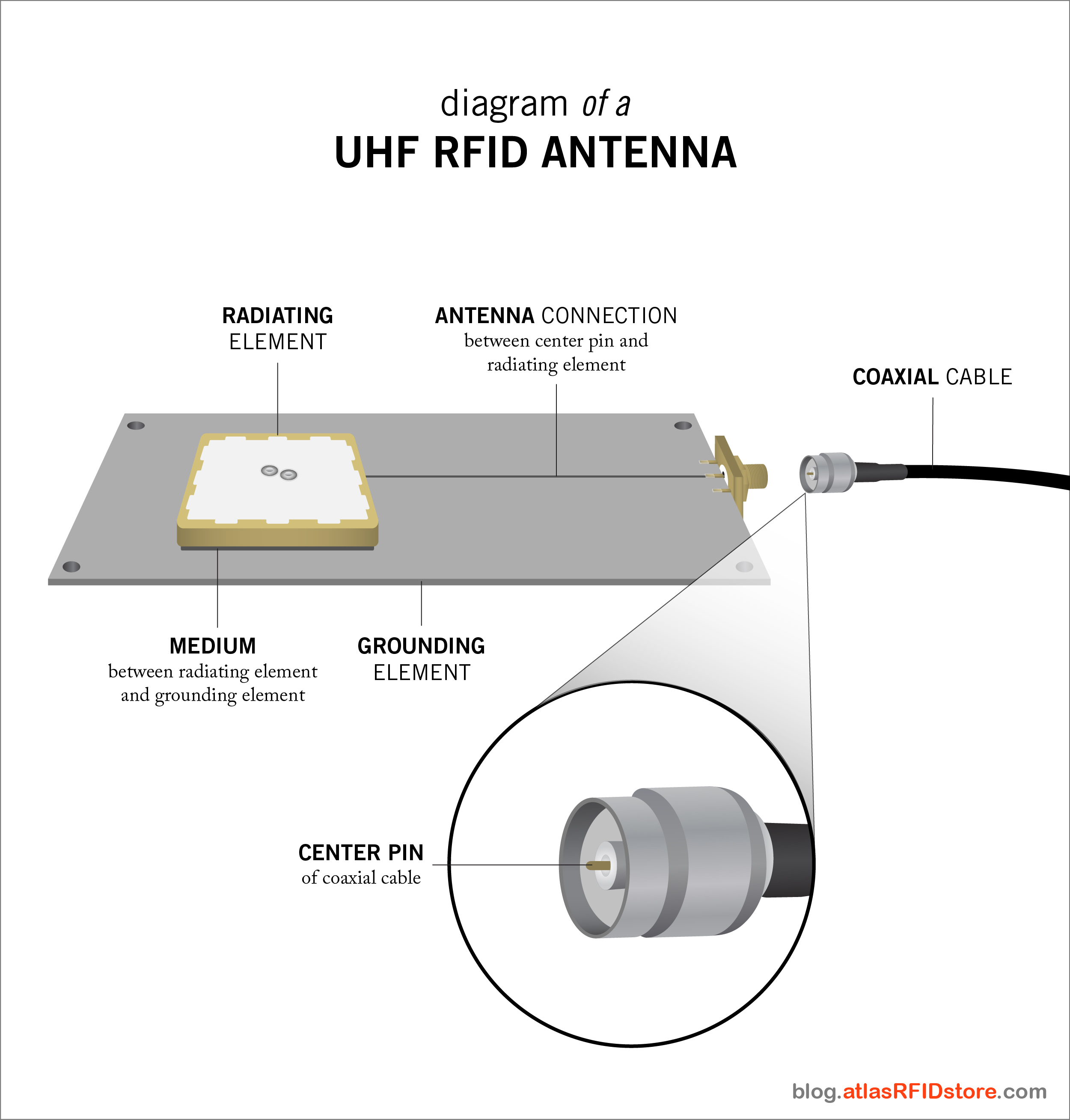
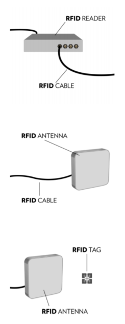
Energy enters an RFID reader through a power cord or Ethernet connection and is directed through the RFID reader, out one of the antenna ports and into the center pin of an RFID cable. It is then sent through the length of the cable and, depending on length and insulation rating of the cable, a small amount of energy is lost due to cable loss. Energy then moves through the opposite center pin, through the center antenna connection located on the grounding plate and into the radiating element. It is then radiated out in the form of RF waves toward the RFID tag in range.
The size and area of the RF waves depend on the gain and beamwidth of the antenna along with the size of the elements inside the antenna like the grounding and radiating plates. Each antenna is made with different elements so each one will radiate the waves differently in some aspect or another.
The waves are received by the RFID tag’s antenna, sent to the integrated chip, and modulated with the pertinent information such as EPC or TID number. The tag then uses the leftover energy to backscatter RF waves back to the antenna. That information is then sent back through the antenna and cable and is decoded within the RFID reader.
Circular or Linear
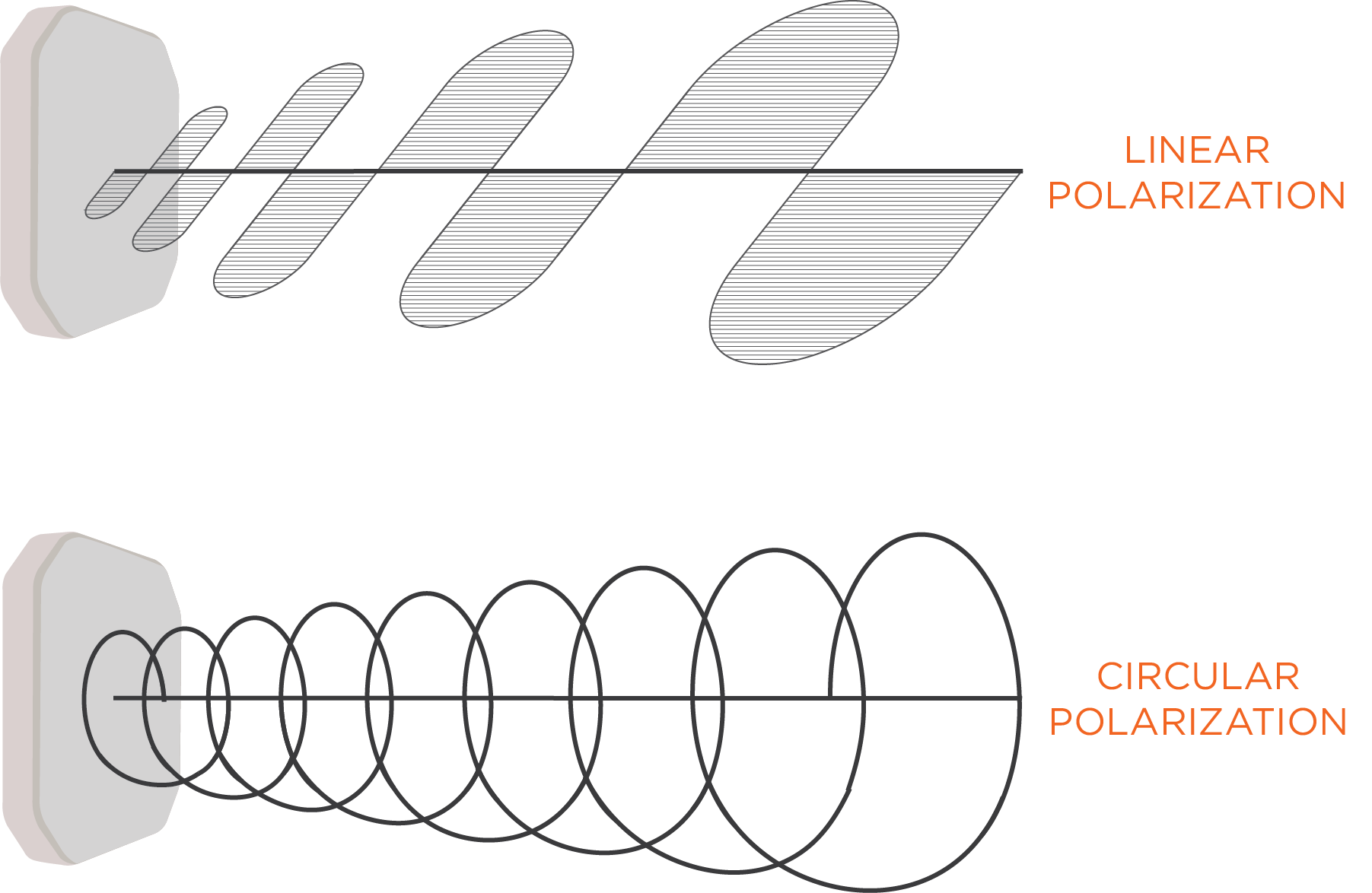
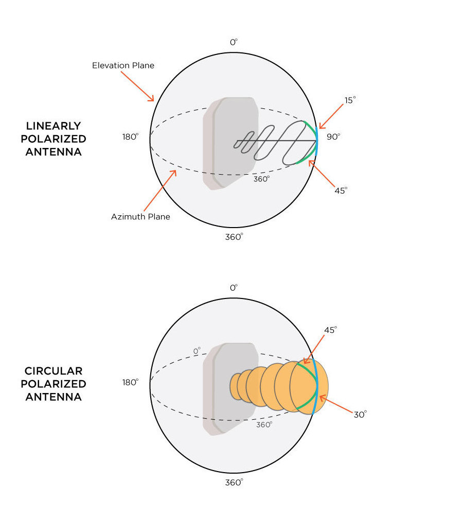
Because RFID antennas radiate and receive RF waves, polarization is an important factor to consider when choosing an RFID antenna. Polarization applies to waves and is basically the geometrical direction of the wave’s oscillation. RF waves generally oscillate in a single direction which can be described as linear, or in a rotating pattern which can be described as circular. Below is an illustration that shows the difference between radiating waves linearly and radiating waves circularly.
Where this is important for an RFID application is how the waves radiate and line up with an RFID tag’s antenna. A circularly polarized antenna works well for applications where the tagged item’s location will not be known or will be at different angles and heights. Because the field rotates, it allows for a little more positional uncertainty for the tagged items (e.g. reading tags on palletized boxes moving through a dock door portal). Linearly polarized antennas are not as flexible with tag angles and heights. If a linearly polarized antenna is radiating waves on a horizontal plane, the receiving tag should be horizontal as well and at a consistent height (e.g. reading tags on rail cars). The same idea applies for linearly polarized antennas that radiate waves on vertical planes.
Two types of circularly polarized antennas exist and are differentiated by the way that they rotate: Right-Hand Circularly Polarized (RHCP) antennas rotate counter-clock wise, and Left-Hand Circularly Polarized (LHCP) antennas rotate clockwise. The choice between LHCP and RHCP only matters when there are two RFID systems with two separate RFID readers in a small area. If two RHCP antennas are facing each other in two separate systems, the waves could collide and cause a large null zone in the middle where no tags will be read. In this case, when these are facing, it would be important to choose one LHCP and one RHCP in order to create the best RF environment.
Key takeaway: Choosing a linearly polarized antenna or a circularly polarized antenna depends on the environment of the application and how the tagged items will pass by the specific antenna. If the tags will be at a constant height and orientation, linear works well, if there is some unknown about the heights and angles, circularly polarized antennas are better. When in doubt, choose a circularly polarized antenna.
RFID Antennas Range - Far Field or Near Field
The most important characteristic of an RFID antenna from a user’s standpoint is usually the read range – i.e. how far the RF waves will radiate in a geometric field. Several factors determine the read range generated by an RFID antenna such as reader transmit power, amount of cable loss, coupling technique, antenna gain, and antenna beamwidth.
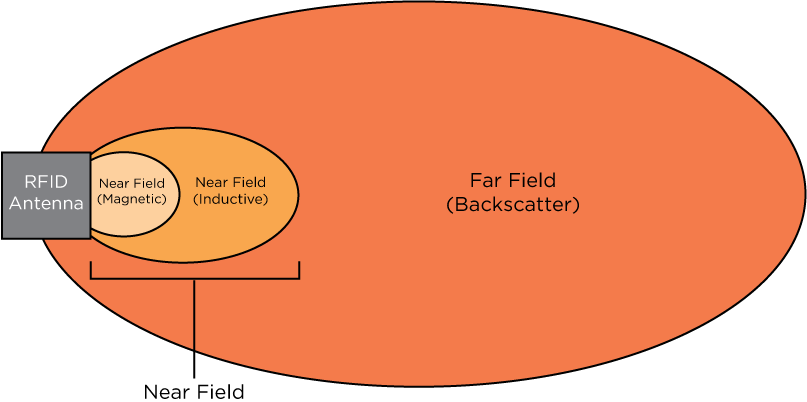
A key aspect of any RFID antenna is whether it is a far-field or near-field antenna. The difference in the two is the way in which they communicate with an RFID tag.
Near-field RFID antennas typically use magnetic or inductive coupling to communicate with the tag when it is the near vicinity. Near-field antennas usually cannot read more than a foot away at the most because their magnetic field and the tag antenna’s magnetic field must be close enough to send and receive information.
Far-field antennas use backscatter to communicate. Backscatter is a communication method in which the antenna sends energy to the tag, which powers the integrated circuit (IC). The IC then modulates the information and sends it back using the remaining energy. Far-field antennas can communicate with passive RFID tags up to 30 feet or more in an optimal environment.
Long read range is not always optimal. In an application with limited space, a greater read range could cause problems due to reading too many tags at once (i.e. “stray” tag reads), instead of one specific tag or group of tags.
Key takeaway: Determine how far away the tagged items will be from the antenna in order to establish if a far field or near field antenna would be best for an application. An application requiring proximity reads will generally benefit from a near field antenna.
What is RFID Antenna Gain?
Antenna gain is expressed in decibels (dB) and is a logarithmic unit of measurement of the ratio of two powers. Gain can be expressed as a few different units of measure such as dB, dBi, dBd, dBm, or dBW which makes it a little more complicated to define. The difference in the unit conveyed (dB, dBi, etc.) explains which two ratios are being measured. Antenna gains cannot be adequately compared in two different units of measure.
dB–The antenna’s power output measured against the power input into the antenna.
dBm–The antenna’s power output measured against 1 milliwatt of power
dBW–The antenna’s power output measured against 1 Watt of power.
dBi–Antenna gain expressed in dBi and is basically the measurement of the amount of power required to produce a certain field of electromagnetic waves in comparison to a “perfect” (no loss, isotropic) antenna’s ability to produce the same field. (dBi = dBd + 2.15)
dBd–The antenna’s power output measured against the gain of a halfwave dipole antenna.
Key takeaway: Decide how much read range is required in order to fulfill your application’s needs. Factor in antenna gain accordingly, and be sure to compare antenna gains with like units of measure.
RFID Antenna's Beam: Wide or Narrow
Beamwidth is very closely related to gain and is exactly what the name implies – the width of the beam or RF field. Two fields exist - the azimuth and elevation fields - and they each have a beamwidth which is crucial to understanding where the RF waves will be directed. Linearly polarized antennas have a relatively small beamwidth in one field, and, depending on the gain, between 30 degrees and 360 degree beamwidth in the other. Most linear antennas’ specifications note the elevation and azimuth beamwidths as the same degree due to the fact that the antenna can be physically turned 90 degrees to show the opposite beamwidth.
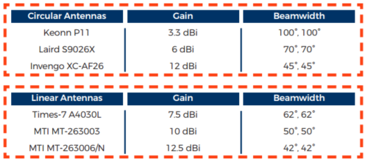
Generally speaking, the higher the gain, the smaller the beamwidth. most users have to decide what is more important for their application, a greater length of read with a small width, or a shorter read length and wider RF field. Some examples are included below.
2D and 3D radiation graphs are illustrations that manufacturers provide and are a “map” of the RF field produced by the antenna. These maps are very helpful in choosing an antenna for a specific application. 2D radiation graphs will have two images – one of the horizontal or azimuth plane and one of the vertical or elevation plane. 3D radiation graphs provide a 3D mapped image of the exact beam pattern in both fields.
Key takeaway: An antenna with a wide beamwidth will generally have a lower gain and cover more area either vertically or horizontally (or both); while a narrow beamwidth will generally have a higher gain and read farther, but cover a smaller area.
What Direction do RFID Antennas Transmit?
Closely related to both gain and beamwidth, directivity is defined as the antenna’s ability to focus in a particular direction to transmit or receive energy. Two different types of antennas exist in relation to directivity: directional and omni-directional. Directional antennas, like the name suggests, have a concentrated beam in one direction. Whether the beamwidth is 25 degrees or 75 degrees, directional antennas focus their gain into a specific direction to pick up tag reads.
Omni-directional antennas provide a wide range of coverage in one plane. Instead of producing a cone-like beam of coverage like directional antennas, omni-directional antennas usually cover one entire plane. Their 3D radiation patterns look similar to doughnuts because they typically have coverage of 360 degrees in one plane and around 20 to 65 degrees in the opposite field. These antennas are made for environments that will see tagged items all at the same height, but may pass the antenna at different angles. Unfortunately, because these antennas have to cover such a large plane, their gain is usually low to lower mid-range.
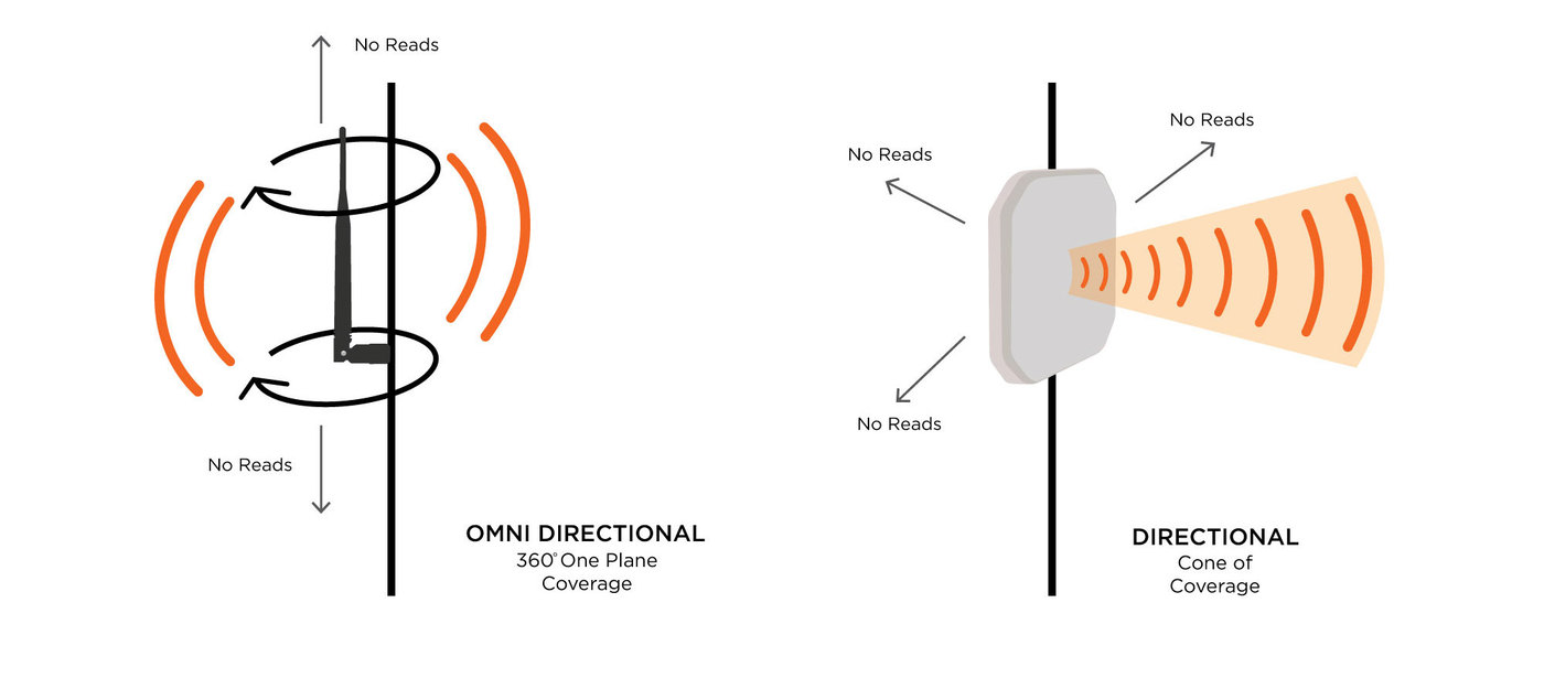
Key takeaway: Directional antennas read in one direction and produce a cone-like field, while omni-directional antennas read 360 degrees on one plane.
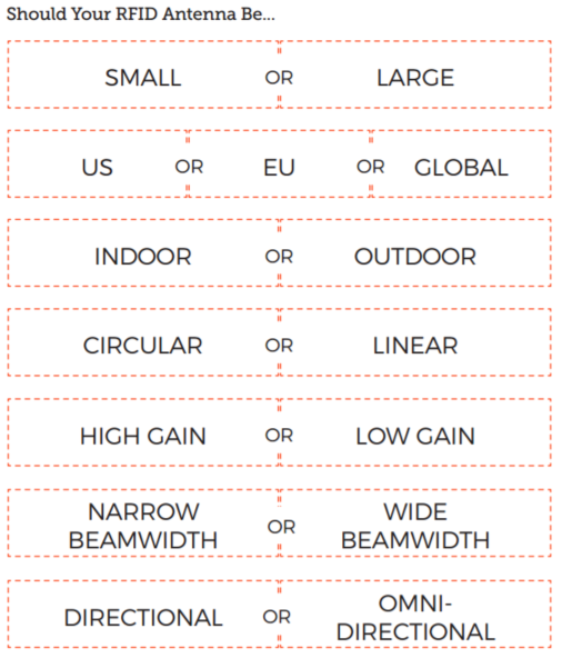
Worksheet: How to Choose an RFID Antenna
After reading the information above, choose the antenna characteristics that best suit your application’s needs. Circling these options will narrow down the possible antenna choices and, ultimately, help determine which antennas should well work for you.
If you have any additional questions about if RFID is right for your application, or about RFID antennas, don't hesitate to contact us.