Explaining Backscatter – From Basic to Advanced Principles
Introduction
This article walks through the basics and advanced principles related to how UHF RFID Passive tags communicate via backscatter. Before reading, it is important to know about the types of coupling and when each one is used. If you do not know what coupling is and how it works, please refer to " Principles of Coupling" before reading this article.
101 - Basics
Backscatter is a method of communication in which an RFID tag without a battery (or any internal power source) receives energy from an RFID reader’s transmission and uses that same energy to send back a reply. The tag receives the energy via electromagnetic waves propagated from the reader/antenna. Once the waves reach the tag, the energy travels through the tag’s internal antenna, and activates the chip, or integrated circuit (IC). The remaining energy is modulated with the chip’s data and flows back via the tag’s antenna to the reader’s antenna in the form of electromagnetic waves.
The best way to understand the principle of backscatter is to imagine two individuals communicating by use of a flashlight and a mirror. In this situation, the flashlight represents the RFID reader, and the mirror represents the RFID tag. The flashlight sends signals to the mirror by turning the beam on and off. While the mirror has no power of its own, it can still communicate in response to the flashlight by reflecting some of the flashlight’s initial signal back. The same basic principle applies to the relationship between an RFID reader and tag – except that when the RFID tag returns the signal back, there are many more options than just all or none (especially when factoring in the ability to filter tag reads using software). (CITE)
Before moving on to the 202 section, you may want to checkout the precursor article below that describes the Operating Principles of Coupling.
202 - Advanced
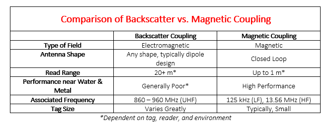
When diving deeper into backscatter, it is impossible to leave out the presence and use of an electric field versus exclusively using a magnetic field. The three most used frequencies for RFID are Low-Frequency (LF), High-Frequency (HF), and Ultra-High Frequency (UHF); but only one of the three, UHF, uses backscatter and, consequently, an electromagnetic field. Extending much further than a magnetic field, an electromagnetic field enables longer read range typically associated with UHF RFID.
Below is a side-by-side comparison of Backscatter Coupling and Magnetic Coupling.
It is important to note that backscatter is a bi-directional communication method – i.e. energy is sent from reader to tag, and then back from tag to reader. Because the same energy is used communicating reader to tag (forward link) and communicating tag to reader (reverse link) we will first talk about the forward link.
Forward Link (UHF)
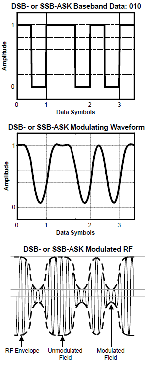
The forward link is the interrogation signal sent out by the reader to energize RFID tags in the field in order to receive a response. The reader modulates an RF signal between 860-960 MHz using DSB-ASK, SSB-ASK, or PR-ASK with PIE encoding. The choice of the frequency is determined by regional radio regulations.
- ASK stands for Amplitude Shift Keying, the most used Keying method for the Forward Link. Amplitude Shift Keying represents a 1 or 0 by shifting the amplitude.
- DSB-ASK stands for Double Sideband ASK which is the most common method of ASK modulation
- SSB-ASK stands for Single Sideband ASK which is used primarily to limit the width of the spectrum occupied.
- PR-ASK stands for Phase Reversal ASK which is also used with different channel widths.
- PIE encoding, or Pulse Interval Encoding is the most common encoding method for the Forward Link.
See source citation below.
Below are representations of encoding & modulation types used for the Forward Link.
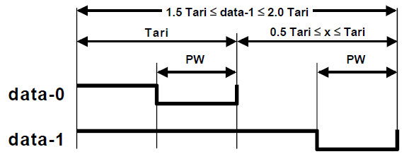
In reference to the graph above, for a binary data of 0, you send a short high pulse followed by a low pulse, and for a data of 1, you send a long high pulse followed by a low pulse. It is done so that the tag does not lose energy in the middle of the communication exchange. If we simply use low voltage for 0 and a high voltage for 1, then a tag ID of say 5000 0000 0000 will receive a whole set of trailing zeroes - i.e. low voltage when the reader is addressing the tag and it might go back to sleep.
See source citation below.
Reverse Link (UHF)
The reverse link is the response signal sent from the tags in the field back to the reader. The tags send back data by switching the reflection coefficient of its antenna between high and low states. The backscatter modulation by the tag will use a fixed modulation format and can be either ASK or PSK. The RFID tags also encode the backscattered data using either FM0 baseband or Miller modulation of a subcarrier at the data rate of transmission. The response back from the tag is detected and decoded at the reader end.
- PSK or Phase Shift Keying can be used in place of ASK in the Reverse Link. Phase Shift Keying represents 0 or a 1 by changes in the phase of the carrier frequency.
- FM0 Baseband, also called Bi-Phase Space Coding, can be used instead of PIE during the Reverse Link
- Miller Encoded Subcarrier can also be used instead of PIE during the Reverse Link
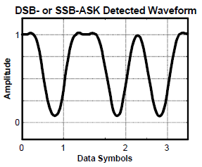
This is the most common modulation type when using ASK during the Reverse Link of communication. This graph shows how data is communicated by changing the amplitude of the wave.
Conclusion
For more information on RFID, comment below or contact us!
If you would like to learn more about all things RFID, check out our website or our YouTube channel.
To read more about RFID concepts, check out the links below!
Below are the main sources for this article.
- Paret, Dominique. RFID at Ultra and Super High Frequencies Theory and Application. Copyright 2009 John Wiley & Sons, Ltd. To find an online version: - https://onlinelibrary.wiley.com/doi/book/10.1002/9780470682135
- Thompson, Dale R. RFID Modulation, Encoding, and Data Rates. Copyright 2008. https://rfidsecurity.uark.edu/downloads/slides/mod04_lesson04_slides.pdf
- Special thanks to Subbu Nambi, RF Engineer at Jovix